|
|

|
224 Physics Lab: Rutherford Scattering
|
223 & 224 Lab Overview |
Return to Physics 224 Labs
Purpose
The purpose of this lab experiment is to perform a modified Rutherford scattering
experiment using macroscopic objects.
Background
In 1910 Sir Ernest Rutherford and his students conducted a famous experiment
whereby the basic construction of the atom became evident. He applied what was
then known about collisions with macroscopic objects to collisions at atomic
dimensions, and proved that atoms must have a central, highly compact nucleus of
positive charge surrounded by a cloud of negatively charged electrons. We will
perform a modified Rutherford experiment in that it presents the
general technique used to determine unknown properties of a scattering target.
| |
| |
|
|
|
|
| |
Figure 1. Three scatterers off a flat surface. Notice
how the scattering angle,
 ,
is not dependent on the impact parameter, ,
is not dependent on the impact parameter,
 . .
|
|
Figure 2. Three scatterers off a circular surface. Notice
how the scattering angle,
,
is dependent on the impact parameter,
.
|
|
Consider two immovable surfaces, one flat and one round, as shown in
Figures 1 and 2. As shown in the Figures, three particles traveling on
parallel paths impact the target's surface, but each particle has a unique impact
parameter,
.
We can detect in what directions each particle rebounds from the surface. After
colliding with the target, the particles are deflected, or scattered,
from their initial direction by some scattering angle,
.
You should note from Figure 1 that the flat surface is characterized by
having each particle scatter from the surface at the same angle: the value
of
is independent of
.
Particles impacting the circular surface, however, scatter according to a precise
mathematical relationship between their impact parameter,
,
and their scattering angle,
.
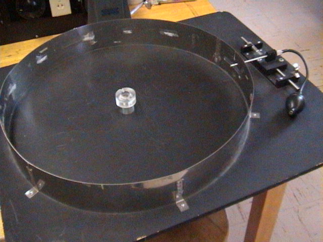
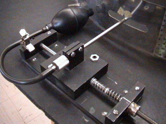
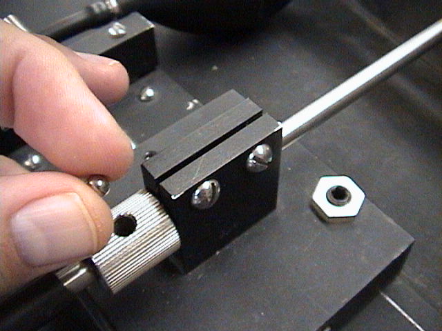
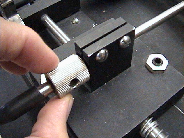
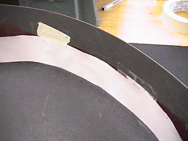
We will use a scattering apparatus to indirectly measure
the radius of a plastic target. An air gun is used to
discharge steel shot at the target, which is rigidly
fixed in the center of large metal rim of radius
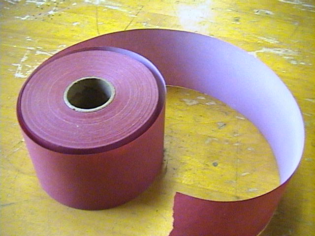
 as shown in Figure 3. By lining the metal rim with a carbon strip, the impact
position of the scattered particles can be recorded and the scattering angle
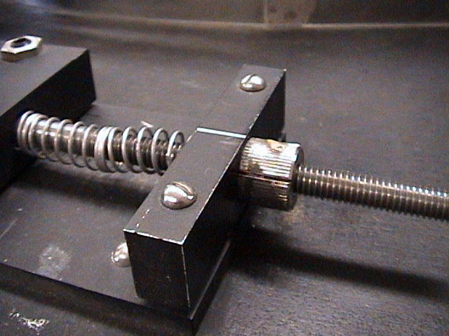
may be determined. The air gun can be set at various impact parameters by adjusting
the travel screw shown in Figure 8.
as shown in Figure 3. By lining the metal rim with a carbon strip, the impact
position of the scattered particles can be recorded and the scattering angle
may be determined. The air gun can be set at various impact parameters by adjusting
the travel screw shown in Figure 8.
| |
|
|
Figure 3. A diagram of the scattering apparatus.
|
If the target's radius is
 ,
then from Figure 3 we find ,
then from Figure 3 we find

|
(1)
|
From Figure 3 it can also be shown that the arclength
 may be represented by
|
(2)
|
where
 and and
 are given in radians, and
is the known radius of the metal rim enclosing the scattering apparatus.
You should be able to convince yourself of this relationship if you recall the
that the arclength,
are given in radians, and
is the known radius of the metal rim enclosing the scattering apparatus.
You should be able to convince yourself of this relationship if you recall the
that the arclength,
 ,
that subtends an angle, ,
that subtends an angle,
 ,
of a circle of radius,
,
is given by the formula ,
of a circle of radius,
,
is given by the formula
 . .
Therefore, if values for
and
can be deduced or indirectly measured, we can determine the value for
.
From Figure 3, we see that
and
are related by
 and Equation 1 then becomes
|
(3)
|
Using the trigonometric identity,
 ,
Equation 3 simplifies to ,
Equation 3 simplifies to

|
(4)
|
Thus a relationship between the target's radius, the impact parameter and the
scattering angle is established for circular targets.
During this experiment, keep in mind that like Rutherford before
you, the dimensions of your target are to remain "invisible". That is, in this
experiment you are not allowed to directly measure the target's diameter or
radius! However, you do know, a priori, that the scattering target is
exactly centered within the metal ring and you may use that fact to assist
your investigation.
Objectives
- Determine the radius of the scattering target. Remember, you are not allowed
to directly measure the target's radius, except when determining the
accuracy of your experimental results.
Equipment and setup
Hints and Cautions
- Caution!!! Do not place your arms, hands or face into the scattering
apparatus as the velocity of the steel shot is quite large.
- Caution!!! When inserting the steel shot into the air gun chamber, be
certain to rotate the chamber closed before firing the gun. Failure to do so
may result in the projectile exiting the chamber and impacting your face!
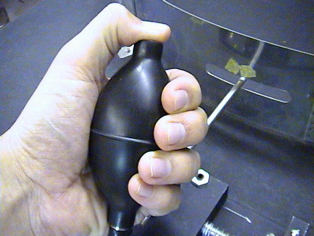
- The success of this experiment is greatly dependent on the force with which
the air gun bulb is squeezed. To produce reproducible results, be consistent
with the force with which you squeeze the bulb.
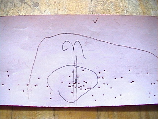
- Do not be discouraged if your data looks very scattered. Try your best to
pinpoint the average impact point for each impact parameter value. Remember,
scattering experiments are expected to show a distribution
of impact points.
- Before beginning the experiment, verify that your air gun shoots straight
by firing the steel shot so that it misses the target. The impact points
should be close together. If not, alert your TA before proceeding!
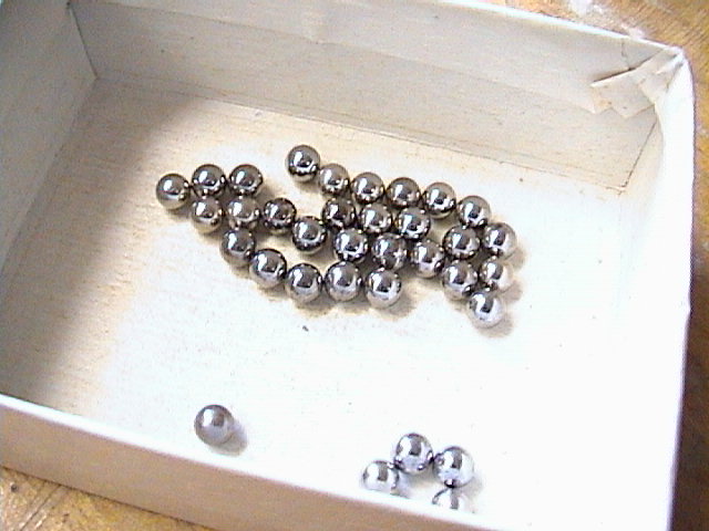
- Keep track of your steel shot (the BB).
Online Assistance
- A much more complicated (and realistic) scattering experiment
- Clemson Physics Lab Tutorials
Lab Report Template
Each lab group should
download the Lab Report Template
and fill in the relevant information
as you perform the experiment. Each person in the group
should print-out the Questions section and answer them individually.
Since each lab group will turn in an electronic copy of the lab report,
be sure to rename the lab report template file. The naming convention is as
follows:
[Table Number][Short Experiment Name].doc.
For example the group at lab
table #5 working on the Ideal Gas Law experiment would rename their template file
as "5 Gas Law.doc".
Questions
Each student should
download the questions.
Each person in the group
should print out the questions and answer them individually.
Discussing the questions as a group is acceptable, but each student is responsible
for turning in answers that represent their own work, not the work of others.
Nudge Questions
These Nudge Questions are to
be answered by your group and checked by your TA as you do the lab. They
should be answered in your lab notebook.
Objective 1 Nudges
- What are the units for angles, arclengths and displacements in this experiment?
- What assumptions must you make regarding the target, air gun and metal rim
for this experiment? Are these assumptions valid?
- What is the radius of the large metal rim?
- How many pieces of carbon paper should you use for this experiment?
- How far around the metal rim should you wrap the carbon paper?
- Are your results dependent on the force with which you fire the air gun?
- How will you determine the position of the gun when
= 0?
- Is it necessary to place a mark on the carbon paper at the
= 0 position?
- How will you measure the impact parameter,
?
Is this the most accurate method?
- How many launches will you make for each
?
- How many values for
will you use for this experiment?
- Is it necessary for each impact parameter,
,
to be equally spaced?
- How will you determine the value for angle
as shown in Figure 3?
How is related to
?
- How is
related to
 , the arclength
subtended by angle ? , the arclength
subtended by angle ?
- Can you directly measure
from the markings on the carbon paper?
- How are the arclengths,
and
,
related to the impact position points on the carbon paper?
- How is the arclength
related to ,
and ?
- What parameters will you plot to determine the radius of the target,
?
- How does your indirect measurement of the target radius,
,
compare to the direct measurement?
- What are the uncertainties in your measurements?
- What is the uncertainty in your value for ?
TA Notes
- Read the Hints and Cautions section!
- Hand out only one steel shot per lab group -- otherwise, the floor
will be covered in BB's!
Data, Results and Graphs
Answers to Questions
Lab Manual
CUPOL Experiments
Vernier caliper tutorial.
If you have a question or comment, send an e-mail to Lab Coordiantor:
Jerry Hester
223 & 224 Lab Overview |
Return to Physics 224 Labs
|
|