|
|

|
223 Physics Lab: Sample Lab
|
223 & 224 Lab Overview |
Return to Physics Labs
 Background
A typical simple pendulum consists of a heavy pendulum bob
(mass =  )
suspended from a light
string. It is generally assumed that the mass of the string is negligible. If the
bob is pulled away from the vertical with some angle, )
suspended from a light
string. It is generally assumed that the mass of the string is negligible. If the
bob is pulled away from the vertical with some angle,
 ,
and released so that the pendulum swings within a vertical plane, the period of the
pendulum is given as: ,
and released so that the pendulum swings within a vertical plane, the period of the
pendulum is given as:
|
(1)
|
where
 is the length of the pendulum and
 is the acceleration due to earth's gravity. Note only the first three
terms in the infinite series is given in Equation 1.
The period is defined as the time required for the
pendulum to complete one oscillation. That is, if the pendulum is released at some
point, P, the period is defined as the time required for the pendulum to swing along
its path and return to point P.
is the acceleration due to earth's gravity. Note only the first three
terms in the infinite series is given in Equation 1.
The period is defined as the time required for the
pendulum to complete one oscillation. That is, if the pendulum is released at some
point, P, the period is defined as the time required for the pendulum to swing along
its path and return to point P.
The above formula for the pendulum's period is greatly simplified if we limit the
initial angle
to small values. If
is small, we can approximate the period of the pendulum with
a first-order expression, which, in the case of our simple pendulum is
given as:

|
(2)
|
Note that the period in this expression is independent of the pendulum's mass
as initial angle,
.
It is important to understand that the above equation is valid only in the
small angle approximation.
Objectives
- Determine the maximum angle for which the first-order expression (Equation
2) for the period of a simple pendulum (Equation 1) is valid.
In other words, ascertain the
cutoff angle for when small angle approximation fails.
- Use a simple pendulum to determine the value of g, the
acceleration due to earth's gravity.
Equipment and setup
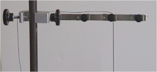
- (Figure 1.) The pendulum stand, clamp and bob.
- (Figure 2.) The pendulum string is secured with the
pendulum clamp. Notice that it is not necessary to tie knots in
the string.
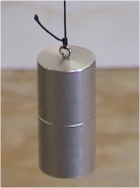
- (Figure 3.) The pendulum bob is an aluminum rod. The bob's
center of mass is marked.
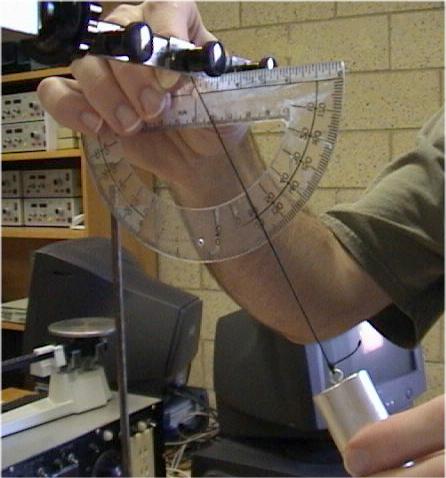
- (Figure 4.) A protractor is used to determine the initial
angle that the pendulum string makes with the vertical.
- (Figures 5, 6 & 7.) As the pendulum swings, a stopwatch or
computer timing device is used to measure the pendulum's period.
- (Figures 6 & 7.) The computer timing devices shown in these
figures are found on our physics lab web page (Figure 6) and also
in the Lab Programs folder found on the computer desk tops of
each laboratory computer (Figure 7).
- (Figure 8.) The meter sticks are located in the window
well at the front of the classroom.
|
[Click on images to enlarge.]
|
Hints and Cautions
- Do not tie knots in the pendulum string. Instead, use the pendulum
clamp to set the pendulum to the desired length.
Online Assistance
- Stopwatch
timer
- Clemson Physics Lab Tutorials
- Using significant figures
- Measurement
uncertainties
- Using Excel
- Graphing data
using Excel
- Adding a trendline
to an Excel plot
- Fitting multiple
curves (trendlines) to one data set
- Using error
bars in Excel
Lab Report Template
Each lab group should
download the Lab Report Template
and fill in the relevant information
as you perform the experiment. Each person in the group
should print-out the Questions section and answer them individually.
Since each lab group will turn in an electronic copy of the lab report,
be sure to rename the lab report template file. The naming convention is as
follows:
[Table Number][Short Experiment Name].doc.
For example the group at lab
table #5 working on the Ideal Gas Law experiment would rename their template file
as "5 Gas Law.doc".
Nudge Questions
These Nudge Questions are to
be answered by your group and checked by your TA as you do the lab. They
should be answered in your lab notebook.
General Nudges
- What method did you use to determine the initial angle of the pendulum?
- What is the uncertainty of the timing device?
- What is the uncertainty of your measurement of the period of the pendulum?
- What steps did you take to decrease the uncertainty in the measurement
of the period?
- What is the uncertainty in the length measurement?
Objective 1 Nudges
- What method will you use to determine the cut-off angle?
- Would the length of the pendulum affect the uncertainty
of the period and length measurements?
Objective 2 Nudges
- What parameters will you graph in order to measure g?
- Did your best-fit line fall within the data points' error bars? Was this
expected?
- What initial angle will you use when working on the second objective?
Questions
These Questions are also found in the Lab Report Template. They must be answered by
each individual of the group. This is not a team activity. Each person should
attach their own copy to the lab report just prior to handing in the lab to your
TA.
- Describe how the pendulum's period is affected if the bob's mass
is doubled. Halved. Assume the period is independent of
.
- Draw a free-body diagram of the pendulum at the top of this page.
You may ignore
friction forces. Write down the force that drives the system, that is,
the force along the direction of motion.
- A simple pendulum has a mass of 0.750kg and a length of 0.500m. What is
the tension in the string when the pendulum is at an angle of 20°?
- Show that for small angles, the driving force in Question 2 becomes
 . Use the fact that at small angles . Use the fact that at small angles
 ,
and the image of the pendulum at the top of this page
to help you. ,
and the image of the pendulum at the top of this page
to help you.
- Compare the pendulum's restoring force to the restoring force of the
simple harmonic motion of an oscillating mass on a spring.
TA Notes
The experiment was performed
and a sample write-up was "graded" by the laboratory
curator. The write-up and the curator's comments are available for you to
view and refer back to when you write future lab reports.
Data, Results and Graphs
The data for this sample experiment is found in the sample lab report
entitled "5pendulum.doc".
Answers to Questions
The questions for this sample experiment are found in the sample lab report
entitled "5pendulum.doc".
CUPOL Experiments
As of now, there are no
CUPOL experiments
associated with this experiment.
If you have a question or comment, send an e-mail to Lab Coordiantor:
Jerry Hester
223 & 224 Lab Overview |
Return to Physics Labs
|
|